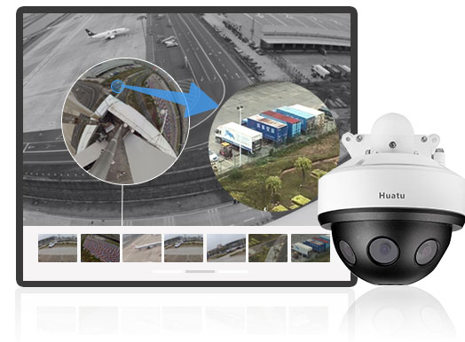
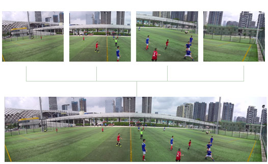
Multi-Sensor Video Stitching is a technology that enables real-time panoramic space roaming experience through real-time video acquisition & stitching & fusion & display. It combines multi-channel video into a large-scale image or 360-degree panorama. Video stitching involves computer vision, computer graphics, digital video processing and some mathematical tools, etc.
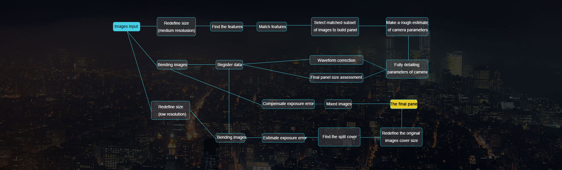
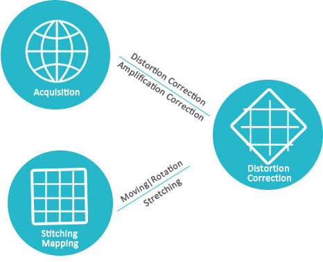
The basic steps of video stitching include the following aspects: synchronous acquisition of multi-channel video, camera calibration, sensor image distortion correction, image projection transformation, matching point selection, panoramic image stitching fusion, and brightness and color balance.
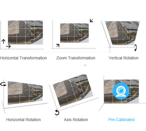
As for the reason of design, assembling and the tolerance between cameras, there are zoom (lens focal length inconsistency), tilt(vertical rotation), azimuth(horizontal rotation) differences between the video images, so the physical differences need to be pre-calibrated to get consistent image and easy to get the subsequent images stitching.
In practical applications, the acquisition of panoramic images often requires cameras to be arranged in different positions and different angles of shooting. For example, due to airborne or vehicle characteristics, the camera is arranged in different ways, it can not guarantee that the camera on the same side, such as cylindrical projection is not necessarily in the same cylinder, the plane projection is not necessarily in the same plane; In addition, in order to avoid blinding spots, the camera tends to tilt downward at a certain angle. These conditions are more common, and easy to be ignored, direct projection and then stitching effect is poor. It is necessary to obtain the coordinate transformed images according to the camera's position information and the angle information before all the images are projected onto a cylinder (or plane).
Theoretically, as long as to meet the static three-dimensional image or plane, the corresponding relationship of the two images can be represent by the projection transformation matrix, in other words, as long as any one of these conditions to meet, images taken by a camera can be represented by coordinate transformation as images taken by another virtual camera.
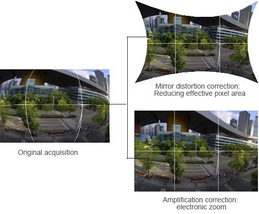
Due to manufacturing, assembly, workmanship etc, there are various distortion phenomenon of image. In order to improve the accuracy of the camera stitching, the imaging lens distortion must be considered when making the image stitching. The general distortion is divided into internal distortion and external distortion.
The internal distortion is due to the the structure of the photography itself, the external distortion is due to the geometric factors of projection method. Lens distortion is an internal distortion, the distortion generated by the lens can be divided into radial distortion and tangential distortion. Radial distortion is the aberration of geometric optics, mainly due to the different radial curvature of the lens, there are barrel distortion and pillow distortion these two types. Tangential distortion is generally considered to be caused by the not collinear optical center of lens set, including various generating errors and assembly errors. It is generally believed that, in the process of optical system imaging, radial distortion is the main factor leading to image distortion.
Since each image is captured by the camera at different angles, they are not on the same projection plane. If the overlapped images are seamlessly stitched directly, the visual consistency of the actual scene will be destroyed. So images need to be projected and transformed firstly, and then stitched. Generally, there are plane projection, cylindrical projection, cube projection and spherical projection.
The plane projection is based on the coordinate system of an image in the sequence image, and the image is projected into the reference coordinate system, so that the overlapping area of the adjacent image is aligned, and this stitching is plane projection stitching; Cylindrical projection refers to such projection stitching that the acquisition of image data re-projection to a cylinder with focal length of camera, and then make the projection of the panorama on the cylinder surface; Spherical projection is to simulate the characteristics of human eye observation, project image information onto the eye part through the perspective of transformation projection, construct as an spherical of observation; Cube projection is a kind of projection stitching method developed to solve the shortcomings of the data storage in spherical allusions, it is suitable for computer-generated images, but for the real shot images is more difficult. As shown in Figure 4, the images stitching process flow diagram.
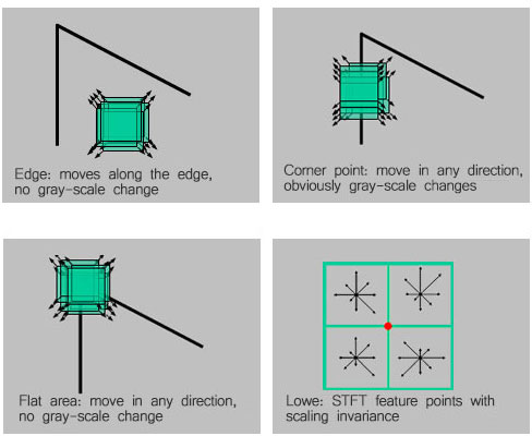
Because the feature points method is easier to deal with the transformation between images, such as rotation, affine, perspective and so on, it is often used. The feature points include the corners of the images and the points of interest that show some singularity relative to their fields. Harris et al. proposed a corner detection algorithm, which is a well-known corner detection algorithm with rigid transformation invariance and affine transformation invariance to a certain degree, but the algorithm does not have a zoom transformation invariance. For such shortcoming, Lowe proposed an SIFT feature points with zoom invariance.
As shown in Figure 5, the image stitching requires finding valid feature matching points in the image sequence. The search for feature points of the image directly affect the accuracy and efficiency of image stitching. For the image sequence, if the number of feature points ≥ 4, it is easy to automatically calibrate the image matching points; if the feature points are few, image stitching often can not achieve more ideal results.
The two key steps of image stitching are registration and fusion. The purpose of registration is to register the image into the same coordinate system according to the geometric motion mode. Fusion is to combine the image into a large stitching image after registration.
In the process of multiple images registration, the geometric motion models mainly are translation model, similarity model, affine model and perspective model.
Image translation model refers to the image displacement of the horizontal and vertical direction and only in these two dimensions, if the camera only has translational motion, you can use the translation model. Image similarity model refers to that the camera itself may has rotational motion in addition to the translational motion. At the same time, it can also be described by the zoom factor and multiplication motion in the presence of scene zoom, so that similarity model can be used when the image is likely to has translational motion, rotational motion, and zooming motion. Image affine model is a 6-parameter transformation model, that is, Image affine model has the general characteristic of parallel lines are transformed into parallel lines and finite point mapping to finite point, the specific performance can be the uniform scale transformation and the non-uniform scale transformation and the shear transformation of the uniform scale transformation coefficients in different directions, etc, it can be used to describe the translational motion, rotational motion and a small range of scaling and deformation. Image perspective model is a transformation model with eight parameters, which can be a perfect representation of all kinds of table changes, and it is the most accurate transformation model.
Image fusion technology can be divided into non-multi-resolution technology and multi-resolution technology. Non-multi-resolution technology mainly includes average method, hat function method, weighted average method and median filter method. Multi-resolution technology mainly includes gaussian pyramid, laplacian pyramid, contrast pyramid, gradient pyramid and wavelet.
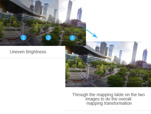
Because the difference of the camera and light intensity, it will cause the uneven brightness within the image and between this image and another image, stitched image will appear bright and dark alternately, this caused great inconvenience to the users.
The usual processing way of brightness and color balance is to correct a picture of the internal light unevenness through the camera light model, and then through the relationship of overlap region between the two adjacent images to establish histogram mapping table of two adjacent images, then through the mapping table on the two images to do the overall mapping transformation, and finally to achieve the overall brightness and color consistency.